If you crack open an arcade cabinet you'll probably be disappointed to find very little inside, your average cabinet will have only four main parts:
- Display - a classic CRT (cathode ray tube) screen or a more modern LCD
- Controls - A joystick and some buttons, under these will be a bunch of switches which give you that satisfying click.
- Board - This is the game, some chips and components on a PCB
- Coin Mech and Bucket - Every kids mortal enemy
The wiring harness will most likely be to the JAMMA (Japan Amusement Machine and Marketing Association) standard. JAMMA introduced the standard in 1985; by the 1990s, most new arcade games were built to JAMMA specifications. As the majority of arcade games were designed in Japan at this time, JAMMA became the de facto standard internationally.
There are a few exceptions (especially on pre 1985 machines) and things that aren't supported by JAMMA (like stereo sound) will have other connectors from the main board.
Anyway, the rest of the machine is just wood and vinyl graphics. This means that you can separate the main components from the massive wooden box and make something that a little more home friendly a SuperGun!
One of the things my company does is test, repair, refurbish and resell arcades. I've found that it's a lot simpler to test an arcade PCB on the bench then in the cabinet so a SuperGun is a must have.
Parts
To build one you're going to need some parts:
First we're going to need a power supply, these are easily available form eBay, shipped from China for about £10

Next is a JAMMA harness, these go for less than £10, this comes with spade and other connectors already wired, very useful when rewiring a cabinet.

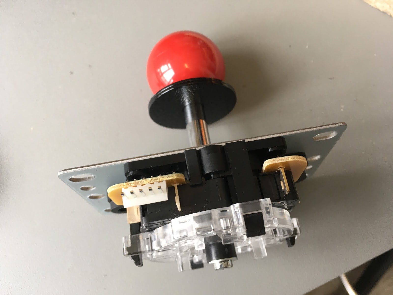
We're going to need some controls, first I got a microswitched joystick with a PCB for about £4, ebay again.
Some buttons, if you're building a full sized Supergun with proper arcade buttons then you'll be spending a bit more, I'm looking for something that first and foremost is for testing so I dont need real switched buttons. these little push buttons will do fine, shipped from China for less than 20p each.

A speaker, the audio out from the board will be line level, so I will probably need to put and inline amplifier in also but I will cross that bridge later, for now I'll still be able to hear the audio with this little guy. Had this kicking around for a while but any 4 or 8 ohm speak will do.

The RGB and SYNC signal from the board will be able to go straight to any TV so I'm going to use some RCA connectors to break out the signal, with the audio and then use a RCA to SCART cable to connect to the Supergun.

A box! One of the things we like to do at 16BitBench is make unusual gaming objects, so I found this box for £8 in a local shop and thought it would do nicely, I actually had my heart set on a lovely painted Indian box with a peacock on the top but it was twice the price and half the size.

The JAMMA pinout, (google it) so we know what wires go where.

Assembly
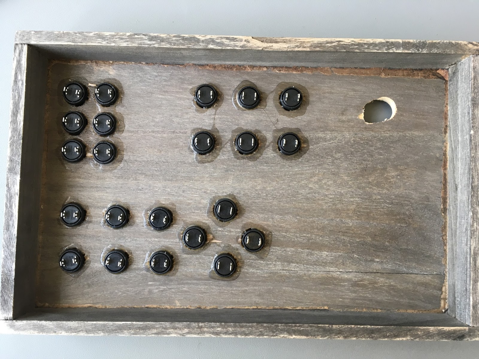
First I'm going to layout my control on the top of the box so I can get the approximate spacing, I'm having six buttons, Although only three are supported in basic JAMMA and four for Neo Geo JAMMA cards there are also machines that will support 6 buttons direct from the PCB, buttons four and five will not be connected up yet. I'm also only using one joystick for player one, player two will just have four button for up, down, left and right. Then there will be six buttons in three pairs for P1 coin, P2 coin, P1 start, P2 start, P1 select and P2 select (select is also Neo Geo only function).
I've stuck a sheet of A4 over the top of the lid and marked the button positions. the main buttons are 30mm apart, the P2 directional and the other control buttons are 20mm apart. No real reason for this is just felt right when i had them laid out on the lid.

Using a 5mm drill bit I've drilled through the paper for the pilot holes.

I'm then using a stepped drill bit to punch out the the size of the buttons, the buttons are 15mm in diameter, my stepped but is only even increments so the holes are 16mm.

The test fit of the first button is nice a snug.

And here we come across our first issue. the thickness of the lid means that the thread on the buttons doesn't come out the back.

So it's not possible to get the nut to bite on the thread. I'll need to think of something else, the holes aren't tight enough for all the button to just push fit, so without securing them they will pop out if the box is inverted.

Problem number two is that the hole for the joystick is too close to the side of the box by about 5mm, I've drilled the hole out bigger to allow for more room. Fortunately this wont be seen as there is a collar for the joystick that will cover the hole.

So all the buttons are fitted, we're going to need to glue, I've turn them parallel so they are all nice and neat because something inside me is a bit OCD.

The wood is nice a light with a large grain so I can tell it will take PVA well, I reckon that if I give each button a collar of PVA that should be enough to hold them in. I add the glue then give each button a 720 degree turn to make sure the glue is between the button and the edge of the hole.

Then I clamp the lid to the 16BitBench this pushes the buttons tight against the lid top while the glue dries. PVA is a pain in the arse and should be given 24 hours, I started this job around midday and by 4pm I could tell the glue was drying (slowly), the workshop is currently nice and warm because the heating cannot be adjusted so hopefully we should be good come tomorrow morning.

Okay the next day and the glue is dry, the buttons are nice and secure, and this will be more than enough to hold these buttons in for a few years yet.

The buttons all share a common ground, so it's just a case of daisy chaining the ground wire, adding a few cross connects as required and leaving a lead for the joystick. I then run a multimeter in continuity mode around the whole thing to make sure there is a good connection to every point required.

We're ready to layout the JAMMA cable, the cable is tied in to groups with player 1 and player 2 control kept together, power, sound and coin mech all are grouped.

The player 1 and 2 control groups, most of the soldering will be for these cables.

Keeping the pinout to hand I go round each button and wire it accordingly.

I've removed the PCB from the joystick body so i can solder it without the joystick getting in the way, I've desoldered the header from the PCB so I can solder direct to it.

Now the wiring is complete for the control I can add the joystick in.

I've run the speaker cable to the speaker and secured it in place with some cable clips.

Now we can tidy our wires, using cable ties to keep everything neat and shortening and resoldering cables as required.

These are the power connections which will be going to the PSU.

I've secured the joystick in place with some bolts. To keep the bolts flush with the top of the lid I've countersunk the holes with a counter sink bit.


I cut a hole for the speak with a holesaw bit, noting that it needs to be smaller than the speaker otherwise it will pop though the hole.


Now I'm going to fit the power supply. it has lugs on the bottom which I'll secure with some more bolts

It's a bit tight to get a drill into the box to drill out, so i use a centre punch to punch a small hole out then drill from the outside in.

The lugs on the power supply are a bit small for the bolts I want to use so I need to drill them a bit bigger.

With a metal drill bit

I use a pair of pliers to hold the lug together then drill the slot bigger.

Once the PSU is fitted I run out the power cable and secure it in place with a cable clip into the thick corner.


There are a couple of wires I'm not too sure what to do with, there's a tilt wire on the harness and a service switch, I figure i can just use this old microswitch on the service wire, and will leave the tilt unconnected for the time being.

And that's pretty much that, I use a few more cable ties to keep everything neat and take look at how much length I have left on the JAMMA, this looks good to me.

I've hooked up a multi arcade emulator card so I can test the output.

And here we go some Wonderboy on my new Supergun.

As you can see from the photo above I'm using the VGA out from the card rather than the RGB from the JAMMA. I'm looking into a small break out box with some RCA connectors that I'll then connect to with a SCART but these bits are still in the post. Also I need to cover the speaker hole with a grill as that open hole is a problem. I'll keep and eye out for something suitable.
I've made a short video showing it working and talking about the process.
https://youtu.be/InLYYeiIWKY
Thanks,
Matt.